
Main
| Characteristic | Value(s) |
|---|---|
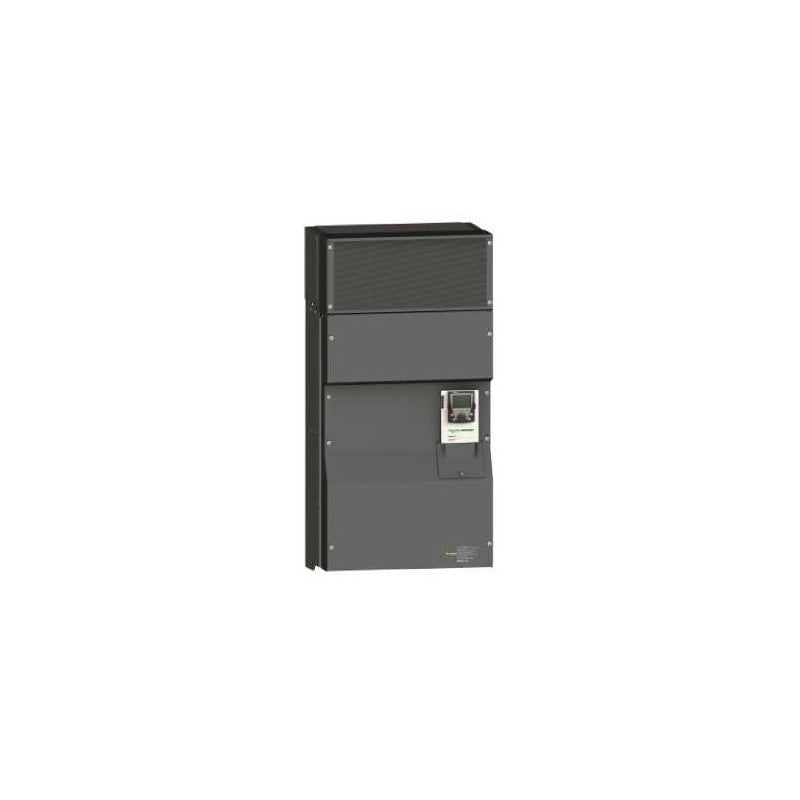
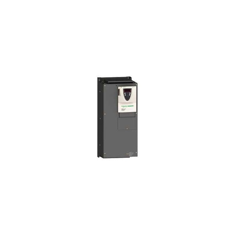
| Range of Product | Altivar 71 |
| Product or Component Type | Variable speed drive |
| Product Specific Application | Complex, high-power machines |
| Component name | ATV71 |
| Motor power kW | 200 kW, 3 phase 380...480 V |
| Maximum Horse Power Rating | 300 hp, 3 phase 380...480 V |
| Maximum motor cable length | 328.08 ft (100 m) shielded cable 656.2 ft (200 m) unshielded cable |
| power supply voltage | 380...480 V - 15...10 % |
| Phase | 3 phase |
| Line current | 286 A 480 V 3 phase 200 kW / 300 hp 357 A 380 V 3 phase 200 kW / 300 hp |
| EMC filter | Integrated |
| Assembly style | With heat sink |
| Variant | Reinforced version |
| Apparent power | 235 kVA 380 V 3 phase 200 kW / 300 hp |
| Prospective line Isc | 50 kA 3 phase |
| Nominal output current | 387 A 2.5 kHz 380 V 3 phase 200 kW / 300 hp 387 A 2.5 kHz 460 V 3 phase 200 kW / 300 hp |
| Maximum transient current | 580 A 60 s 3 phase 200 kW / 300 hp 638 A 2 s 3 phase 200 kW / 300 hp |
| Output frequency | 0.1â¦500 Hz |
| Nominal switching frequency | 2.5 kHz |
| Switching frequency | 2.5...8 kHz adjustable 2.5...8 kHz with derating factor |
| Asynchronous motor control profile | Sensorless flux vector control (SFVC) (voltage or current vector) Flux vector control (FVC) with sensor (current vector) ENA (Energy adaptation) system for unbalanced loads Voltage/frequency ratio (2 or 5 points) |
| Type of polarization | No impedance Modbus |
Complementary
| Characteristic | Value(s) |
|---|---|
| Product destination | Synchronous motors Asynchronous motors |
| power supply voltage limits | 323â¦528 V |
| power supply frequency | 50...60 Hz - 5...5 % |
| power supply frequency limits | 47.5...63 Hz |
| Speed range | 1â¦100 asynchronous motor in open-loop mode, without speed feedback 1â¦1000 asynchronous motor in closed-loop mode with encoder feedback 1â¦50 synchronous motor in open-loop mode, without speed feedback |
| Speed accuracy | +/- 0.01 % of nominal speed in closed-loop mode with encoder feedback 0.2 Tn to Tn +/- 10 % of nominal slip without speed feedback 0.2 Tn to Tn |
| Torque accuracy | +/- 15 % in open-loop mode, without speed feedback +/- 5 % in closed-loop mode with encoder feedback |
| Transient overtorque | 170 % +/- 10 % 60 s every 10 minutes 220 % +/- 10 % 2 s |
| Braking torque | <= 150 % with braking or hoist resistor 30 % without braking resistor |
| Synchronous motor control profile | Vector control without speed feedback |
| Regulation loop | Adjustable PI regulator |
| Motor slip compensation | Suppressable Not available in voltage/frequency ratio (2 or 5 points) Adjustable Automatic whatever the load |
| diagnostic | 1 LED (red) for drive voltage |
| Output voltage | <= power supply voltage |
| Insulation | Electrical between power and control |
| type of cable for mounting in an enclosure | With a NEMA Type1 kit 3 UL 508 cable 104 °F (40 °C), copper 75 °C / PVC With an IP21 or an IP31 kit 3 IEC cable 104 °F (40 °C), copper 70 °C / PVC Without mounting kit 1 IEC cable 113 °F (45 °C), copper 70 °C / PVC Without mounting kit 1 IEC cable 113 °F (45 °C), copper 90 °C / XLPE/EPR |
| Electrical connection | Terminal 2.5 mm², AWG 14 AI1-/AI1+, AI2, AO1, R1A, R1B, R1C, R2A, R2B, LI1...LI6, PWR) Terminal 4 x 185 mm² L1/R, L2/S, L3/T, U/T1, V/T2, W/T3) Terminal 4 x 185 mm² PC/-, PA/+) |
| Tightening torque | 5.3 lbf.in (0.6 N.m) AI1-/AI1+, AI2, AO1, R1A, R1B, R1C, R2A, R2B, LI1...LI6, PWR) 362.9 lbf.in (41 N.m), 360 lb.in L1/R, L2/S, L3/T, U/T1, V/T2, W/T3) 362.9 lbf.in (41 N.m), 360 lb.in PC/-, PA/+) |
| Supply | Internal supply for reference potentiometer (1 to 10 kOhm) 10.5 V DC +/- 5 %, <10 mA overload and short-circuit protection Internal supply 24 V DC 21â¦27 V), <200 mA overload and short-circuit protection |
| Analogue input number | 2 |
| Analogue input type | AI1-/Al1+ bipolar differential voltage +/- 10 V DC 24 V max 11 bits + sign AI2 software-configurable current 0...20 mA 242 Ohm 11 bits AI2 software-configurable voltage 0...10 V DC 24 V max 30000 Ohm 11 bits |
| input sampling time | 2 ms +/- 0.5 ms AI1-/Al1+) - analog 2 ms +/- 0.5 ms Al2) - analog 2 ms +/- 0.5 ms LI1...LI5) - discrete 2 ms +/- 0.5 ms LI6)if configured as logic input - discrete |
| Response time | <= 100 ms in STO (Safe Torque Off) AO1 2 ms +/- 0.5 ms analog R1A, R1B, R1C 7 ms +/- 0.5 ms discrete R2A, R2B 7 ms +/- 0.5 ms discrete |
| absolute accuracy precision | +/- 0.6 % AI1-/Al1+) for a temperature variation 60 °C +/- 0.6 % AI2) for a temperature variation 60 °C +/- 1 % AO1) for a temperature variation 60 °C |
| Linearity error | +/- 0.15 % of maximum value AI1-/Al1+, AI2) +/- 0.2 % AO1) |
| Analogue output number | 1 |
| Analogue output type | AO1 software-configurable logic output 10 V 20 mA AO1 software-configurable current 0...20 mA 500 Ohm 10 bits AO1 software-configurable voltage 0...10 V DC 470 Ohm 10 bits |
| Discrete output number | 2 |
| Discrete output type | Configurable relay logic R1A, R1B, R1C) NO/NC - 100000 cycles Configurable relay logic R2A, R2B) NO - 100000 cycles |
| Minimum switching current | 3 mA 24 V DC configurable relay logic |
| Maximum switching current | R1, R2 2 A 250 V AC inductive, cos phi = 0.4 R1, R2 2 A 30 V DC inductive, cos phi = 0.4 R1, R2 5 A 250 V AC resistive, cos phi = 1 R1, R2 5 A 30 V DC resistive, cos phi = 1 |
| Discrete input number | 7 |
| Discrete input type | LI1...LI5 programmable 24 V DC level 1 PLC 3500 Ohm LI6 switch-configurable 24 V DC level 1 PLC 3500 Ohm LI6 switch-configurable PTC probe 0â¦6 1500 Ohm PWR safety input 24 V DC 1500 Ohm ISO 13849-1 level d |
| Discrete input logic | Negative logic (sink) LI1...LI5), > 16 V, < 10 V Positive logic (source) LI1...LI5), < 5 V, > 11 V Negative logic (sink) LI6)if configured as logic input, > 16 V, < 10 V Positive logic (source) LI6)if configured as logic input, < 5 V, > 11 V |
| Acceleration and deceleration ramps | S, U or customized Linear adjustable separately from 0.01 to 9000 s Automatic adaptation of ramp if braking capacity exceeded, by using resistor |
| Braking to standstill | By DC injection |
| Protection type | Against exceeding limit speed drive Against input phase loss drive Break on the control circuit drive Input phase breaks drive Line supply overvoltage drive Line supply undervoltage drive Overcurrent between output phases and earth drive Overheating protection drive Overvoltages on the DC bus drive Short-circuit between motor phases drive Thermal protection drive Motor phase break motor Power removal motor Thermal protection motor |
| Insulation resistance | > 1 mOhm 500 V DC for 1 minute to earth |
| Frequency resolution | Analog input 0.024/50 Hz Display unit 0.1 Hz |
| Communication Port Protocol | CANopen Modbus |
| Connector type | 1 RJ45 on front face)Modbus 1 RJ45 on terminal)Modbus Male SUB-D 9 on RJ45CANopen |
| Physical interface | 2-wire RS 485 Modbus |
| Transmission frame | RTU Modbus |
| Transmission rate | 4800 bps, 9600 bps, 19200 bps, 38.4 Kbps Modbus on terminal 9600 bps, 19200 bps Modbus on front face 20 kbps, 50 kbps, 125 kbps, 250 kbps, 500 kbps, 1 Mbps CANopen |
| Data format | 8 bits, 1 stop, even parity Modbus on front face 8 bits, odd even or no configurable parity Modbus on terminal |
| Number of addresses | 1â¦127 CANopen 1â¦247 Modbus |
| Method of access | Slave CANopen |
| Marking | CE |
| Operating position | Vertical +/- 10 degree |
| Height | 46.9 in (1190 mm) |
| Depth | 14.8 in (377 mm) |
| Width | 23.4 in (595 mm) |
| Product Weight | 456.4 lb(US) (207 kg) |
| Functionality | Full |
| Specific application | Other applications |
| Option card | Communication card CC-Link Controller inside programmable card Communication card DeviceNet Communication card EtherNet/IP Communication card Fipio I/O extension card Communication card Interbus-S Interface card for encoder Communication card Modbus Plus Communication card Modbus TCP Communication card Modbus/Uni-Telway Overhead crane card Communication card Profibus DP Communication card Profibus DP V1 |
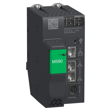
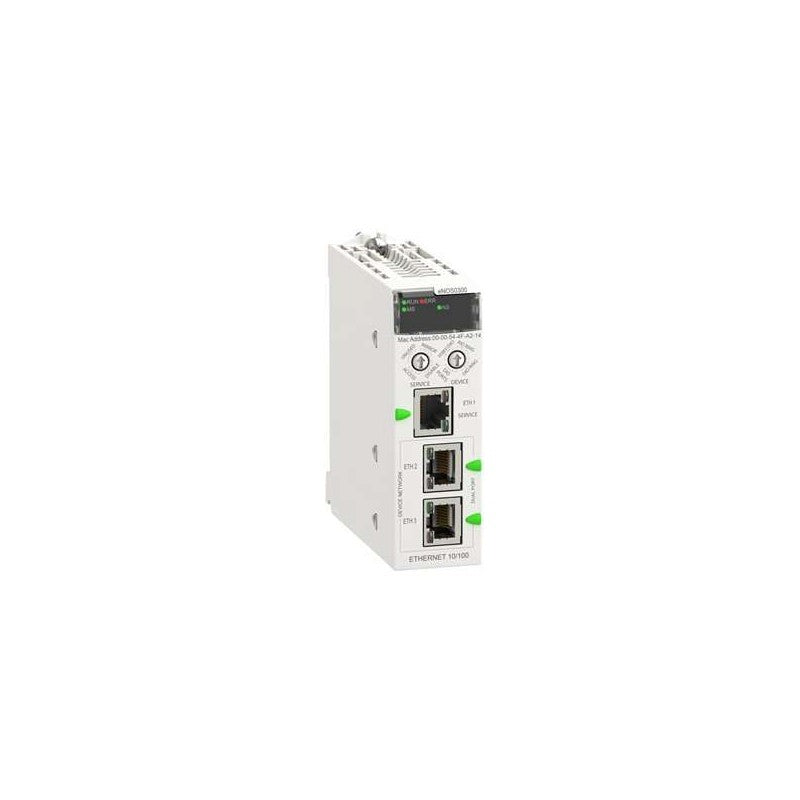
Redundant Processor, Modicon M580, 64Mb, 61 Ethernet Devices, 31 Remote Io Racks Of X80 And Quantum Io
Redundant HSBY processor module M580 - Level 4 - Remote
Main
| Characteristic | Value(s) |
|---|---|
| Range of Product | Modicon Quantum automation platform |
| Product or Component Type | Unity processor |
Complementary
| Characteristic | Value(s) |
|---|---|
| Mode of Transmission | Multi mode |
| Clock frequency | 266 MHz |
| Number of slots | 10 16 4 6 2 |
| Number of racks | 2 - local |
| Number of distributed I/O station | 63 1 3 Modbus Plus |
| Number of remote I/O station | 31 - 2 S908 remote I/O 31 - 2 ethernet Quantum remote I/O 31 - 2 ethernet X80 remote I/O |
| Discrete I/O number | 31744 inputs, 31744 outputs - remote 8000 inputs, 8000 outputs - distributed - per network Modbus Plus Unlimited (31 drops of 28 slots max) - ethernet remote I/O 0 - local - forbidden in Hot Standby application |
| Analogue I/O number | 500 inputs, 500 outputs - distributed - per network Modbus Plus Unlimited (31 drops of 28 slots max) - ethernet remote I/O 1984 inputs,1984 outputs - remote 0 - local - forbidden in Hot Standby application |
| Application specific I/O | Accurate time stamping Counter Serial link High-speed interrupt inputs |
| Communication Service | Ethernet router |
| Number of optional modules | 6 Ethernet, Modbus, Modbus Plus, Profibus DP, Sy/Max) |
| Maximum number of connections | 1 USB 2 AS-Interface - distributed 4 AS-Interface - remote 6 Ethernet TCP/IP - local 6 Modbus Plus - local 6 Profibus DP - local 1 Modbus RS232/485 Modbus/ASCII) |
| Integrated connection type | 1 Modbus Plus 1 Modbus 1 USB 1 optic fibre Hot Standby |
| Checks | Process control Hot standby |
| Memory description | Expandable 7168 kB - program with PCMCIA card Expandable 8 MB - file storage with PCMCIA card Internal RAM 3072 kB - 1536 kB for data |
| Switch Function | Key switch memory port on/off |
| Application structure | 1 periodic fast task - forbidden in Hot Standby application 128 I/O interrupt tasks - forbidden in Hot Standby application 128 interrupt tasks - forbidden in Hot Standby application 32 timer interrupt tasks - forbidden in Hot Standby application 4 auxiliary tasks - forbidden in Hot Standby application 1 cyclic/periodic master task - |
| Number of instructions per ms | 10.28 Kinst/ms 100 % Boolean 10.07 Kinst/ms 65 % Boolean and 35 % numerical |
| System overhead | 0.2 ms fast task 1 ms master task |
| Bus current requirement | 2760 mA |
| Local signalling | for Ethernet activity (COM) 1 LED (yellow) 1 LED (yellow) for configuration status (STS) |
| Electrical connection | 1 female connector SUB-D 9 for connecting to the Modbus Plus network 1 connector RJ45 for connecting Modbus bus 1 connector MT-RJ (multimode fiber optic) for interconnecting primary and secondary PLCs up to 4 km |
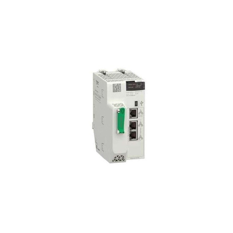
This product is part of the Modicon M580 range, an offer of Programmable Automation Controllers (PAC) and safety Programmable Logic Controllers (PLC) with built-in Ethernet. This processor module offers a maximum of 4 rack configuration and 72 application specific channels. It is a processor module with a current consumption of 270mA at 24V DC. It supports 2048 discrete, 512 analogue local I/O channels and 128 distributed equipment. It is furnished with Ethernet TCP/IP for service port, 2 Ethernet TCP/IP for device network, Ethernet for HSBY port and USB type mini B for integrated connections. It offers 600000 hours of MTBF. It has an integrated RAM of 8MB for program, 768kb for data, 10kb for system and expandable flash of 4GB for data storage. It is an IP20 rated product. It weighs 0.849kg. It is suitable for medium to large process applications. This product is certified by CE, Merchant Navy, UL, RCM, CSA, EAC. It meets EN 61131-2, EN 61000-6-4, EN 61000-6-2 and EN 61010-2-201 standards. The benefits of Modicon M580 are reduce time to market, improve reliability and sustainability, improve productivity with high performance and increase operating profitability due to improved access to data.
Main
| Characteristic | Value(s) |
|---|---|
| Range of Product | Modicon M580 |
| Product or Component Type | Processor module |
Complementary
| Characteristic | Value(s) |
|---|---|
| Number of racks | 4 |
| Local I/O processor capacity (discrete) | 2048 I/O |
| Local I/O processor capacity (analog) | 512 I/O |
| Number of application specific channel (local rack) | 72 |
| Application specific I/O | HART SSI encoder Motion control Serial link Accurate time stamping Counter |
| Checks | Process control |
| Control channels | Programmable loops |
| Integrated connection type | 1 Ethernet TCP/IP service port 2 Ethernet TCP/IP device network USB type mini B |
| Number of distributed equipment | 128 |
| Communication module processor capacity | 2 Ethernet communication module 4 AS-Interface module |
| Communication Service | DIO scanner |
| Memory description | Expandable flash, 4 GB data storage Integrated RAM, 10 kB system memory Integrated RAM, 8 MB program Integrated RAM, 768 kB data |
| Application structure | 1 cyclic/periodic master task 64 event tasks 2 auxiliary tasks 1 periodic fast task |
| Cybersecurity | Achilles certified DoS prevention IPSec SNMP logging Syslog protocol support Transport layer security Audit trail Embedded firewall Firmware signature Password protection Port hardening Secure communication (HTTPS) Security log |
| Number of instructions per ms | 30 Kinst/ms 65 % Boolean + 35 % fixed arithmetic 40 Kinst/ms 100 % Boolean |
| Current consumption | 270 mA 24 V DC |
| MTBF reliability | 775000 H |
| Marking | CE |
Main
| Characteristic | Value(s) |
|---|---|
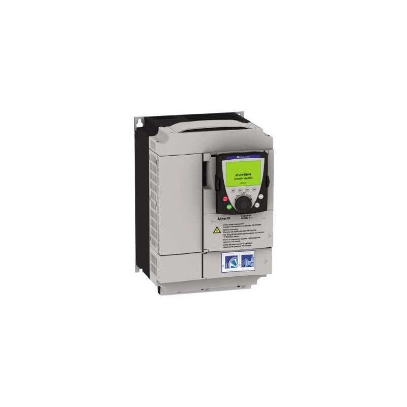
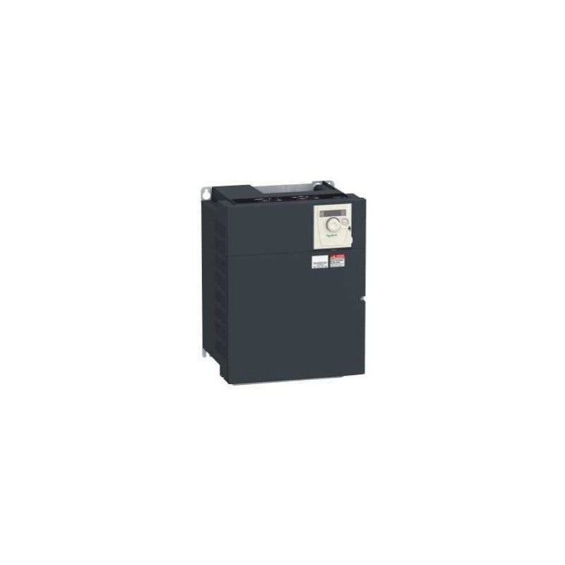
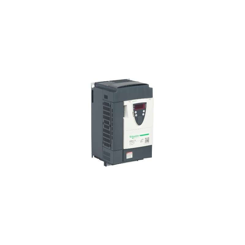
| Range of Product | Altivar 61 |
| Product or Component Type | Variable speed drive |
| Product Specific Application | Pumping and ventilation machine |
| Component name | ATV61 |
| Motor power kW | 18.5 kW, 3 phase 380...480 V |
| Maximum Horse Power Rating | 25 hp, 3 phase 380...480 V |
| power supply voltage | 380...480 V - 15...10 % |
| supply number of phases | 3 phase |
| Line current | 37.5 A 480 V 3 phase 18.5 kW / 25 hp 45.5 A 380 V 3 phase 18.5 kW / 25 hp |
| EMC filter | Level 3 EMC filter |
| Assembly style | With heat sink |
| Apparent power | 29.9 kVA 380 V 3 phase 18.5 kW / 25 hp |
| maximum prospective line Isc | 22 kA 3 phase |
| Maximum transient current | 49.2 A 60 s, 3 phase |
| Nominal switching frequency | 12 kHz |
| Switching frequency | 1...16 kHz adjustable 12...16 kHz with derating factor |
| asynchronous motor control | Voltage/frequency ratio, 5 points Voltage/frequency ratio, 2 points Flux vector control without sensor, standard Voltage/frequency ratio - Energy Saving, quadratic U/f |
| Synchronous motor control profile | Vector control without sensor, standard |
| Communication Port Protocol | CANopen Modbus |
| Type of polarization | No impedance Modbus |
| Option card | Communication card APOGEE FLN Communication card BACnet Communication card CC-Link Controller inside programmable card Communication card DeviceNet Communication card EtherNet/IP Communication card Fipio I/O extension card Communication card Interbus-S Communication card LonWorks Communication card METASYS N2 Communication card Modbus Plus Communication card Modbus TCP Communication card Modbus/Uni-Telway Multi-pump card Communication card Profibus DP Communication card Profibus DP V1 |
Complementary
| Characteristic | Value(s) |
|---|---|
| Product destination | Synchronous motors Asynchronous motors |
| power supply voltage limits | 323â¦528 V |
| power supply frequency | 50...60 Hz - 5...5 % |
| power supply frequency limits | 47.5...63 Hz |
| Continuous output current | 34 A 12 kHz, 460 V - 3 phase 41 A 12 kHz, 380 V - 3 phase |
| Output frequency | 0.1â¦599 Hz |
| Speed range | 1â¦100 in open-loop mode, without speed feedback |
| Speed accuracy | +/- 10 % of nominal slip 0.2 Tn to Tn without speed feedback |
| Torque accuracy | +/- 15 % in open-loop mode, without speed feedback |
| Transient overtorque | 130 % of nominal motor torque +/- 10 % 60 s |
| Braking torque | <= 125 % with braking resistor 30 % without braking resistor |
| Regulation loop | Frequency PI regulator |
| Motor slip compensation | Adjustable Can be suppressed Not available in voltage/frequency ratio (2 or 5 points) Automatic whatever the load |
| diagnostic | 1 LED (red) for drive voltage |
| Output voltage | <= power supply voltage |
| electrical isolation | Between power and control terminals |
| type of cable for mounting in an enclosure | With an IP21 or an IP31 kit 3 IEC cable 104 °F (40 °C), copper 70 °C / PVC With UL Type 1 kit 3 UL 508 cable 104 °F (40 °C), copper 75 °C / PVC Without mounting kit 1 IEC cable 113 °F (45 °C), copper 70 °C / PVC Without mounting kit 1 IEC cable 113 °F (45 °C), copper 90 °C / XLPE/EPR |
| Electrical connection | Terminal 2.5 mm² / AWG 14 AI1-/AI1+, AI2, AO1, R1A, R1B, R1C, R2A, R2B, LI1...LI6, PWR) Terminal 25 mm² / AWG 3 L1/R, L2/S, L3/T, U/T1, V/T2, W/T3, PC/-, PO, PA/+, PA, PB) |
| Tightening torque | 5.3 lbf.in (0.6 N.m) AI1-/AI1+, AI2, AO1, R1A, R1B, R1C, R2A, R2B, LI1...LI6, PWR) 47.8 lbf.in (5.4 N.m), 47.7 lb.in L1/R, L2/S, L3/T, U/T1, V/T2, W/T3, PC/-, PO, PA/+, PA, PB) |
| Supply | Internal supply for reference potentiometer (1 to 10 kOhm) 10.5 V DC, +/- 5 %, <10 mA overload and short-circuit protection Internal supply 24 V DC 21â¦27 V), <200 mA overload and short-circuit protection External supply 24 V DC 19â¦30 V) |
| Analogue input number | 2 |
| Analogue input type | AI1-/Al1+ bipolar differential voltage +/- 10 V DC 24 V max 11 bits + sign AI2 software-configurable current 0...20 mA 242 Ohm 11 bits AI2 software-configurable voltage 0...10 V DC 24 V max 30000 Ohm 11 bits |
| sampling time | 2 ms +/- 0.5 ms AI1-/Al1+) - analog input 2 ms +/- 0.5 ms Al2) - analog input 2 ms +/- 0.5 ms AO1) - analog output 2 ms +/- 0.5 ms LI1...LI5) - discrete input 2 ms +/- 0.5 ms LI6)if configured as logic input - discrete input |
| absolute accuracy precision | +/- 0.6 % AI1-/Al1+) for a temperature variation 60 °C +/- 0.6 % AI2) for a temperature variation 60 °C +/- 1 % AO1) for a temperature variation 60 °C |
| Linearity error | +/- 0.15 % of maximum value AI1-/Al1+) +/- 0.15 % of maximum value AI2) +/- 0.2 % AO1) |
| Analogue output number | 1 |
| Analogue output type | AO1 software-configurable current 0...20 mA 500 Ohm 10 bits AO1 software-configurable voltage 0...10 V DC 470 Ohm 10 bits AO1 software-configurable logic output 10 V, 20 mA |
| Discrete output number | 2 |
| Discrete output type | Configurable relay logic R1A, R1B, R1C) NO/NC - 100000 cycles Configurable relay logic R2A, R2B) NO - 100000 cycles |
| maximum response time | <= 100 ms in STO (Safe Torque Off) R1A, R1B, R1C <= 7 ms +/- 0.5 ms R2A, R2B <= 7 ms +/- 0.5 ms |
| Minimum switching current | 3 mA 24 V DC configurable relay logic |
| Maximum switching current | R1, R2 2 A 250 V AC inductive, cos phi = 0.4 7 ms R1, R2 2 A 30 V DC inductive, cos phi = 0.4 7 ms R1, R2 5 A 250 V AC resistive, cos phi = 1 0 ms R1, R2 5 A 30 V DC resistive, cos phi = 1 0 ms |
| Discrete input number | 7 |
| Discrete input type | Programmable LI1...LI5) 24 V DC <= 30 V)level 1 PLC - 3500 Ohm Switch-configurable LI6) 24 V DC <= 30 V)level 1 PLC - 3500 Ohm Switch-configurable PTC probe LI6)0â¦6 - 1500 Ohm Safety input PWR) 24 V DC <= 30 V) - 1500 Ohm |
| Discrete input logic | Negative logic (sink) LI1...LI5), > 16 V, < 10 V Positive logic (source) LI1...LI5), < 5 V, > 11 V Negative logic (sink) LI6)if configured as logic input, > 16 V, < 10 V Positive logic (source) LI6)if configured as logic input, < 5 V, > 11 V |
| Acceleration and deceleration ramps | Automatic adaptation of ramp if braking capacity exceeded, by using resistor S, U or customized Linear adjustable separately from 0.01 to 9000 s |
| Braking to standstill | By DC injection |
| Protection type | Against exceeding limit speed drive Against input phase loss drive Break on the control circuit drive Input phase breaks drive Line supply overvoltage drive Line supply undervoltage drive Overcurrent between output phases and earth drive Overheating protection drive Overvoltages on the DC bus drive Power removal drive Short-circuit between motor phases drive Thermal protection drive Motor phase break motor Power removal motor Thermal protection motor |
| Insulation resistance | > 1 mOhm 500 V DC for 1 minute to earth |
| Frequency resolution | Analog input 0.024/50 Hz Display unit 0.1 Hz |
| Connector type | 1 RJ45 on front face)Modbus 1 RJ45 on terminal)Modbus Male SUB-D 9 on RJ45CANopen |
| Physical interface | 2-wire RS 485 Modbus |
| Transmission frame | RTU Modbus |
| Transmission rate | 4800 bps, 9600 bps, 19200 bps, 38.4 Kbps Modbus on terminal 9600 bps, 19200 bps Modbus on front face 20 kbps, 50 kbps, 125 kbps, 250 kbps, 500 kbps, 1 Mbps CANopen |
| Data format | 8 bits, 1 stop, even parity Modbus on front face 8 bits, odd even or no configurable parity Modbus on terminal |
| Number of addresses | 1â¦127 CANopen 1â¦247 Modbus |
| Method of access | Slave CANopen |
| Marking | CE |
| Operating position | Vertical +/- 10 degree |
| Product Weight | 48.5 lb(US) (22 kg) |
| Width | 9.06 in (230 mm) |
| Height | 15.7 in (400 mm) |
| Depth | 8.4 in (213 mm) |
Altivar ATV61 variable frequency drives (VFD) are for variable torque applications from 1 to 900 HP. For the latest in high performance drives for pump and fan applications consider using an Altivar Process ATV600 drive family. Conformity to the international standards and certifications: CE, UL, CSA, C-Tick. The Altivar ATV61 is used for fan, multi pump and pump applications.
Main
| Characteristic | Value(s) |
|---|---|
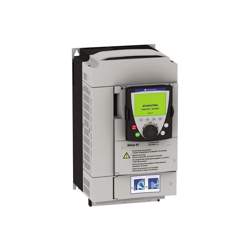
| Range of Product | Altivar 61 |
| Product or Component Type | Variable speed drive |
| Product Specific Application | Pumping and ventilation machine |
| Component name | ATV61 |
| Motor power kW | 7.5 kW, 3 phase 380...480 V |
| Maximum Horse Power Rating | 10 hp, 3 phase 380...480 V |
| power supply voltage | 380...480 V - 15...10 % |
| supply number of phases | 3 phase |
| Line current | 22.2 A 480 V 3 phase 7.5 kW / 10 hp 27 A 380 V 3 phase 7.5 kW / 10 hp |
| EMC filter | Level 3 EMC filter |
| Assembly style | With heat sink |
| Apparent power | 17.8 kVA 380 V 3 phase 7.5 kW / 10 hp |
| maximum prospective line Isc | 22 kA 3 phase |
| Maximum transient current | 21.1 A 60 s, 3 phase |
| Nominal switching frequency | 12 kHz |
| Switching frequency | 1...16 kHz adjustable 12...16 kHz with derating factor |
| asynchronous motor control | Voltage/frequency ratio, 5 points Voltage/frequency ratio, 2 points Voltage/frequency ratio - Energy Saving, quadratic U/f Flux vector control without sensor, standard |
| Synchronous motor control profile | Vector control without sensor, standard |
| Communication Port Protocol | Modbus CANopen |
| Type of polarization | No impedance Modbus |
| Option card | Communication card APOGEE FLN Communication card BACnet Communication card CC-Link Controller inside programmable card Communication card DeviceNet Communication card EtherNet/IP Communication card Fipio I/O extension card Communication card Interbus-S Communication card LonWorks Communication card METASYS N2 Communication card Modbus Plus Communication card Modbus TCP Communication card Modbus/Uni-Telway Multi-pump card Communication card Profibus DP Communication card Profibus DP V1 |
Complementary
| Characteristic | Value(s) |
|---|---|
| Product destination | Synchronous motors Asynchronous motors |
| power supply voltage limits | 323â¦528 V |
| power supply frequency | 50...60 Hz - 5...5 % |
| power supply frequency limits | 47.5...63 Hz |
| Continuous output current | 14 A 12 kHz, 460 V - 3 phase 17.6 A 12 kHz, 380 V - 3 phase |
| Output frequency | 0.1â¦599 Hz |
| Speed range | 1â¦100 in open-loop mode, without speed feedback |
| Speed accuracy | +/- 10 % of nominal slip 0.2 Tn to Tn without speed feedback |
| Torque accuracy | +/- 15 % in open-loop mode, without speed feedback |
| Transient overtorque | 130 % of nominal motor torque +/- 10 % 60 s |
| Braking torque | <= 125 % with braking resistor 30 % without braking resistor |
| Regulation loop | Frequency PI regulator |
| Motor slip compensation | Automatic whatever the load Can be suppressed Adjustable Not available in voltage/frequency ratio (2 or 5 points) |
| diagnostic | 1 LED (red) for drive voltage |
| Output voltage | <= power supply voltage |
| electrical isolation | Between power and control terminals |
| type of cable for mounting in an enclosure | With an IP21 or an IP31 kit 3 IEC cable 104 °F (40 °C), copper 70 °C / PVC With UL Type 1 kit 3 UL 508 cable 104 °F (40 °C), copper 75 °C / PVC Without mounting kit 1 IEC cable 113 °F (45 °C), copper 70 °C / PVC Without mounting kit 1 IEC cable 113 °F (45 °C), copper 90 °C / XLPE/EPR |
| Electrical connection | Terminal 2.5 mm² / AWG 14 AI1-/AI1+, AI2, AO1, R1A, R1B, R1C, R2A, R2B, LI1...LI6, PWR) Terminal 6 mm² / AWG 8 L1/R, L2/S, L3/T, U/T1, V/T2, W/T3, PC/-, PO, PA/+, PA, PB) |
| Tightening torque | 5.3 lbf.in (0.6 N.m) AI1-/AI1+, AI2, AO1, R1A, R1B, R1C, R2A, R2B, LI1...LI6, PWR) 26.6 lbf.in (3 N.m), 26.5 lb.in L1/R, L2/S, L3/T, U/T1, V/T2, W/T3, PC/-, PO, PA/+, PA, PB) |
| Supply | Internal supply for reference potentiometer (1 to 10 kOhm) 10.5 V DC, +/- 5 %, <10 mA overload and short-circuit protection Internal supply 24 V DC 21â¦27 V), <200 mA overload and short-circuit protection External supply 24 V DC 19â¦30 V) |
| Analogue input number | 2 |
| Analogue input type | AI1-/Al1+ bipolar differential voltage +/- 10 V DC 24 V max 11 bits + sign AI2 software-configurable current 0...20 mA 242 Ohm 11 bits AI2 software-configurable voltage 0...10 V DC 24 V max 30000 Ohm 11 bits |
| sampling time | 2 ms +/- 0.5 ms AI1-/Al1+) - analog input 2 ms +/- 0.5 ms Al2) - analog input 2 ms +/- 0.5 ms AO1) - analog output 2 ms +/- 0.5 ms LI1...LI5) - discrete input 2 ms +/- 0.5 ms LI6)if configured as logic input - discrete input |
| absolute accuracy precision | +/- 0.6 % AI1-/Al1+) for a temperature variation 60 °C +/- 0.6 % AI2) for a temperature variation 60 °C +/- 1 % AO1) for a temperature variation 60 °C |
| Linearity error | +/- 0.15 % of maximum value AI1-/Al1+) +/- 0.15 % of maximum value AI2) +/- 0.2 % AO1) |
| Analogue output number | 1 |
| Analogue output type | AO1 software-configurable current 0...20 mA 500 Ohm 10 bits AO1 software-configurable voltage 0...10 V DC 470 Ohm 10 bits AO1 software-configurable logic output 10 V, 20 mA |
| Discrete output number | 2 |
| Discrete output type | Configurable relay logic R1A, R1B, R1C) NO/NC - 100000 cycles Configurable relay logic R2A, R2B) NO - 100000 cycles |
| maximum response time | <= 100 ms in STO (Safe Torque Off) R1A, R1B, R1C <= 7 ms +/- 0.5 ms R2A, R2B <= 7 ms +/- 0.5 ms |
| Minimum switching current | 3 mA 24 V DC configurable relay logic |
| Maximum switching current | R1, R2 2 A 250 V AC inductive, cos phi = 0.4 7 ms R1, R2 2 A 30 V DC inductive, cos phi = 0.4 7 ms R1, R2 5 A 250 V AC resistive, cos phi = 1 0 ms R1, R2 5 A 30 V DC resistive, cos phi = 1 0 ms |
| Discrete input number | 7 |
| Discrete input type | Programmable LI1...LI5) 24 V DC <= 30 V)level 1 PLC - 3500 Ohm Switch-configurable LI6) 24 V DC <= 30 V)level 1 PLC - 3500 Ohm Switch-configurable PTC probe LI6)0â¦6 - 1500 Ohm Safety input PWR) 24 V DC <= 30 V) - 1500 Ohm |
| Discrete input logic | Negative logic (sink) LI1...LI5), > 16 V, < 10 V Positive logic (source) LI1...LI5), < 5 V, > 11 V Negative logic (sink) LI6)if configured as logic input, > 16 V, < 10 V Positive logic (source) LI6)if configured as logic input, < 5 V, > 11 V |
| Acceleration and deceleration ramps | Automatic adaptation of ramp if braking capacity exceeded, by using resistor Linear adjustable separately from 0.01 to 9000 s S, U or customized |
| Braking to standstill | By DC injection |
| Protection type | Against exceeding limit speed drive Against input phase loss drive Break on the control circuit drive Input phase breaks drive Line supply overvoltage drive Line supply undervoltage drive Overcurrent between output phases and earth drive Overheating protection drive Overvoltages on the DC bus drive Power removal drive Short-circuit between motor phases drive Thermal protection drive Motor phase break motor Power removal motor Thermal protection motor |
| Insulation resistance | > 1 mOhm 500 V DC for 1 minute to earth |
| Frequency resolution | Analog input 0.024/50 Hz Display unit 0.1 Hz |
| Connector type | 1 RJ45 on front face)Modbus 1 RJ45 on terminal)Modbus Male SUB-D 9 on RJ45CANopen |
| Physical interface | 2-wire RS 485 Modbus |
| Transmission frame | RTU Modbus |
| Transmission rate | 4800 bps, 9600 bps, 19200 bps, 38.4 Kbps Modbus on terminal 9600 bps, 19200 bps Modbus on front face 20 kbps, 50 kbps, 125 kbps, 250 kbps, 500 kbps, 1 Mbps CANopen |
| Data format | 8 bits, 1 stop, even parity Modbus on front face 8 bits, odd even or no configurable parity Modbus on terminal |
| Number of addresses | 1â¦127 CANopen 1â¦247 Modbus |
| Method of access | Slave CANopen |
| Marking | CE |
| Operating position | Vertical +/- 10 degree |
| Product Weight | 12.1 lb(US) (5.5 kg) |
| Width | 6.9 in (175 mm) |
| Height | 11.6 in (295 mm) |
| Depth | 7.4 in (187 mm) |
Main
| Characteristic | Value(s) |
|---|---|
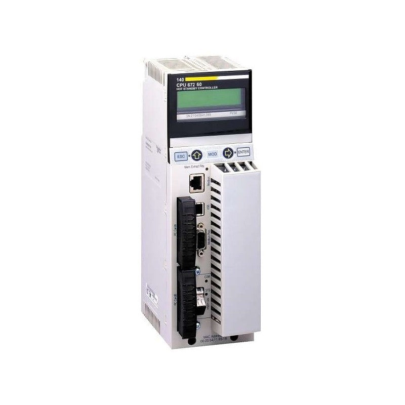
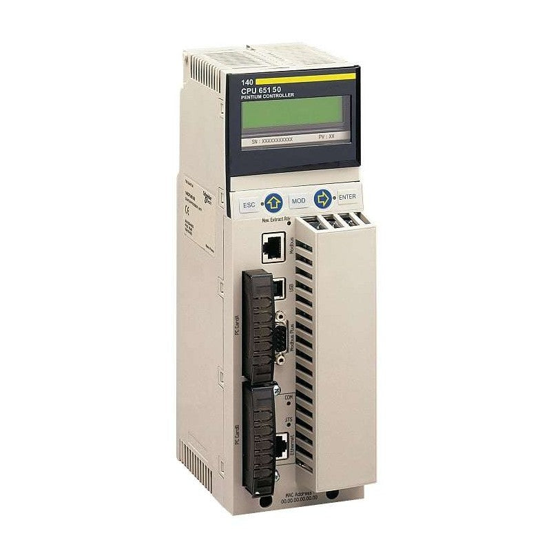
| Range of Product | Modicon Quantum automation platform |
| Product or Component Type | Unity processor |
Complementary
| Characteristic | Value(s) |
|---|---|
| Clock frequency | 166 MHz |
| Number of slots | 10 16 6 4 2 |
| Number of racks | 2 - local |
| Number of distributed I/O station | 63 1 3 Modbus Plus |
| Number of remote I/O station | 31 - 2 S908 remote I/O 31 - 2 ethernet Quantum remote I/O 16 - 2 ethernet X80 remote I/O |
| Discrete I/O number | 31744 inputs, 31744 outputs - remote 8000 inputs, 8000 outputs - distributed - per network Modbus Plus Unlimited (26 slots max) - local Unlimited (31 drops of 28 slots max) - ethernet remote I/O |
| Analogue I/O number | 500 inputs, 500 outputs - distributed - per network Modbus Plus 1984 inputs,1984 outputs - S908 remote I/O Unlimited (26 slots max) - local Unlimited (31 drops of 28 slots max) - ethernet remote I/O |
| Application specific I/O | Accurate time stamping Serial link High-speed interrupt inputs Counter |
| Communication Service | Ethernet router |
| Number of optional modules | 6 Ethernet, Modbus, Modbus Plus, Profibus DP, Sy/Max) |
| Maximum number of connections | 1 USB 2 AS-Interface - distributed 4 AS-Interface - remote 6 Ethernet TCP/IP - local 6 Modbus Plus - local 6 Profibus DP - local 1 Modbus RS232/485 Modbus/ASCII) |
| Integrated connection type | 1 Modbus Plus 1 Ethernet TCP/IP 1 Modbus 1 USB |
| Checks | Process control |
| Memory description | Expandable 7168 kB - program with PCMCIA card Expandable 8 MB - file storage with PCMCIA card Internal RAM 768 kB |
| Switch Function | Key switch memory port on/off |
| Application structure | 1 cyclic/periodic master task - 1 periodic fast task - 128 I/O interrupt tasks - 128 interrupt tasks - 32 timer interrupt tasks - 4 auxiliary tasks - |
| Number of instructions per ms | 10.28 Kinst/ms 100 % Boolean 10.07 Kinst/ms 65 % Boolean and 35 % numerical |
| System overhead | 0.2 ms fast task 1 ms master task |
| Bus current requirement | 2160 mA |
| Local signalling | 1 LED (green) for Ethernet activity (COM) 1 LED (red) for Ethernet collision |
| Electrical connection | 1 female connector SUB-D 9 for connecting to the Modbus Plus network 1 connector RJ45 for connecting Ethernet network 1 connector RJ45 for connecting Modbus bus |
This Lexium 32 Servo Drive Works At A Rated Supply Voltage From 208V Ac To 480V Ac. It Can Feed 3-Phase Synchronous Motors Bmh Or Bsh, Its Continuous Output Current Is 24A At 8Khz. The Compact Size Of The Servo Drive And Associated Servo Motor Provides Maximum Power In The Minimum Space. This Servo Drive Is Specifically Designed For Industrial Machines. It Offers High Performance, Power And Simplicity Of Use In Motion Control Applications. It Complies With International Standards Iec/En 61800-5-1, Iec/En 61800-3, And Is Ul And Csa And Is Ul And Csa Certified And Ce Marked. It Has Been Developed To Meet The Requirements Of Directives Regarding Protection Of The Environment (Ro
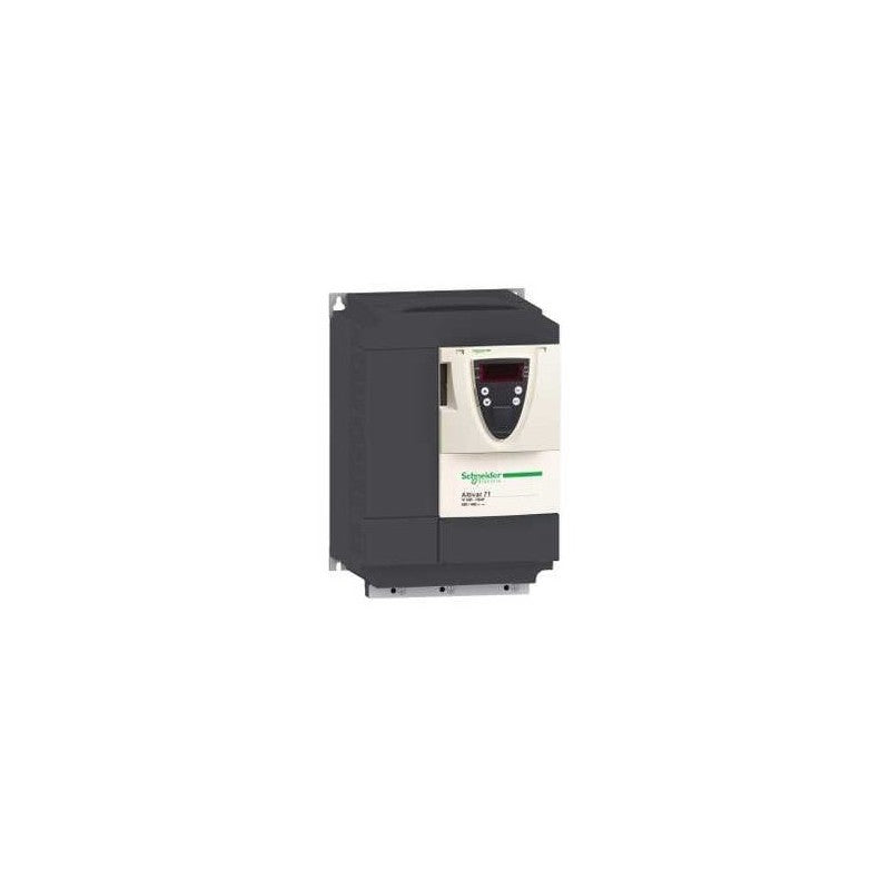
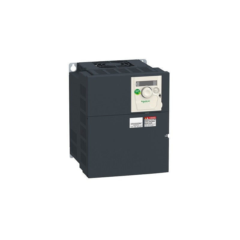
Variable Speed Drive Altivar 71 - 15kW-20hp - 480V - with EMC filter whitout Graphic Terminal
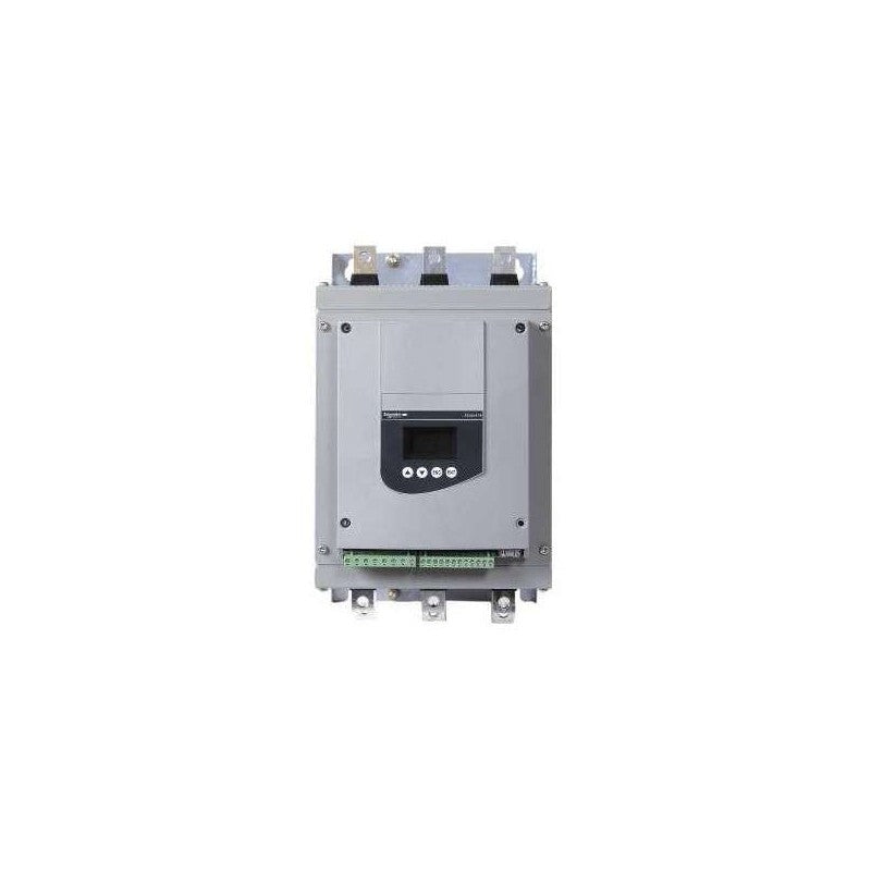
Soft Starter for Asynchronous Motor - Altistart ATS48 - 131 A - 230..415 V - 30..110kW

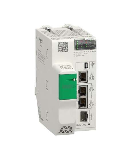
This product is part of the Modicon M580 range, an offer of Programmable Automation Controllers (PAC) and safety Programmable Logic Controllers (PLC) with built-in Ethernet. This processor module offers a maximum of 8 rack configuration and 144 application specific channels. It is a processor module with a current consumption of 295mA at 24V DC. It supports 4096 discrete, 1024 analogue local I/O channels and 64 distributed equipment. It is integrated with Ethernet TCP/IP for service port, 2 Ethernet TCP/IP for device network, Ethernet for HSBY port and USB type mini B for connections. It offers 600000 hours of MTBF. It has 16 - 2 racks per remote drop for I/O station. It has an integrated RAM of 16MB for program, 2048kb for data, 10kb for system memory and expandable flash of 4GB for data storage. It is an IP20 rated product. It weighs 0.849kg. It is suitable for medium to large process applications. This product is certified by CE, Merchant Navy, UL, RCM, CSA, EAC. It meets EN 61131-2, EN 61000-6-4, EN 61000-6-2 and EN 61010-2-201 standards. The benefits of Modicon M580 are reduce time to market, improve reliability and sustainability, improve productivity with high performance and increase operating profitability due to improved access to data.
Main
| Characteristic | Value(s) |
|---|---|
| Range of Product | Modicon M580 |
| Product or Component Type | Processor module |
Complementary
| Characteristic | Value(s) |
|---|---|
| Number of racks | 8 |
| Local I/O processor capacity (discrete) | 4096 I/O |
| Local I/O processor capacity (analog) | 1024 I/O |
| Number of application specific channel (local rack) | 144 |
| Application specific I/O | Counter SSI encoder Motion control Accurate time stamping HART Serial link |
| Checks | Process control |
| Control channels | Programmable loops |
| Integrated connection type | 1 Ethernet TCP/IP service port 2 Ethernet TCP/IP device network USB type mini B |
| Number of remote I/O station | 16 - 2 remote drop |
| Number of distributed equipment | 64 |
| Communication module processor capacity | 16 AS-Interface module 4 Ethernet communication module |
| Communication Service | RIO scanner DIO scanner |
| Memory description | Expandable flash, 4 GB data storage Integrated RAM, 10 kB system memory Integrated RAM, 16 MB program Integrated RAM, 2048 kB data |
| Application structure | 2 auxiliary tasks 1 cyclic/periodic master task 1 periodic fast task 128 event tasks |
| Cybersecurity | Achilles certified DoS prevention IPSec SNMP logging Syslog protocol support Transport layer security Audit trail Embedded firewall Firmware signature Password protection Port hardening Secure communication (HTTPS) Security log |
| Number of instructions per ms | 30 Kinst/ms 65 % Boolean + 35 % fixed arithmetic 40 Kinst/ms 100 % Boolean |
| Current consumption | 295 mA 24 V DC |
| MTBF reliability | 775000 H |
| Marking | CE |
Main
| Characteristic | Value(s) |
|---|---|
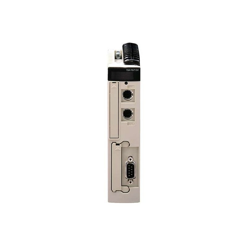
| Range of Product | Modicon Premium Automation platform |
| Product or Component Type | Single-format PL7 processor |
| Software Designation | PL7 Junior/Pro |
Complementary
| Characteristic | Value(s) |
|---|---|
| Number of racks | 2 12 slots 4 4/6/8 slots |
| Number of slots | 24 32 16 |
| Discrete I/O processor capacity | 512 I/O |
| Analogue I/O processor capacity | 24 I/O |
| Number of application specific channel | 8 |
| Integrated connection type | Non isolated serial link 2 female mini DIN19.2 kbit/s) Fipio manager (63 agents) SUB-D 9 |
| Communication module processor capacity | 1 network module 2 AS-Interface bus modules |
| Memory description | Internal RAM (with PCMCIA card) 32 Kwords data Internal RAM (without PCMCIA card) 32 Kwords program and data PCMCIA card 128 Kwords additional data storage PCMCIA card 64 Kwords program |
| Maximum size of object areas | 30.5 %MWi internal words located internal data 32 %KWi constant words located internal data 4096 %Mi located internal bits |
| Application structure | 1 fast task 1 master task 32 event tasks |
| Execution time per instruction | 0.5 µs Boolean without PCMCIA card 0.6 µs Boolean with PCMCIA card 0.62 µs word or fixed-point arithmetic without PCMCIA card 0.87 µs word or fixed-point arithmetic with PCMCIA card 44 µs floating points with PCMCIA card 44 µs floating points without PCMCIA card |
| Number of instructions per ms | 0.85 Kinst/ms 65 % Boolean + 35 % fixed arithmetic with PCMCIA card 1.05 Kinst/ms 65 % Boolean + 35 % fixed arithmetic without PCMCIA card 1.18 Kinst/ms 100 % Boolean with PCMCIA card 1.52 Kinst/ms 100 % Boolean without PCMCIA card |
| System overhead | 0.8 ms fast task 3.1 ms master task |
| Marking | CE |
| Local signalling | 1 LED (green) for processor running (RUN) 1 LED (red) for activity on Fipio bus (FIP) 1 LED (red) for I/O module or configuration fault (I/O) 1 LED (red) for processor or system fault (ERR) 1 LED (yellow) for activity on the terminal port (TER) |
| Current consumption | 8530 mA 5 V DC |
| Module format | Standard |
| Product Weight | 0.93 lb(US) (0.42 kg) |
Main
| Characteristic | Value(s) |
|---|---|
| Range of Product | Altivar 71 |
| Product or Component Type | Variable speed drive |
| Product Specific Application | Complex, high-power machines |
| Component name | ATV71 |
| Motor power kW | 22 kW, 3 phase 380...480 V |
| Maximum Horse Power Rating | 30 hp, 3 phase 380...480 V |
| Maximum motor cable length | 328.08 ft (100 m) shielded cable 656.2 ft (200 m) unshielded cable |
| power supply voltage | 380...480 V - 15...10 % |
| Phase | 3 phase |
| Line current | 42 A 480 V 3 phase 22 kW / 30 hp 50 A 380 V 3 phase 22 kW / 30 hp |
| EMC filter | Integrated |
| Assembly style | With heat sink |
| Variant | Without remote graphic terminal |
| Apparent power | 32.9 kVA 380 V 3 phase 22 kW / 30 hp |
| Prospective line Isc | 22 kA 3 phase |
| Nominal output current | 40 A 4 kHz 460 V 3 phase 22 kW / 30 hp 48 A 4 kHz 380 V 3 phase 22 kW / 30 hp |
| Maximum transient current | 72 A 60 s 3 phase 22 kW / 30 hp 79.2 A 2 s 3 phase 22 kW / 30 hp |
| Output frequency | 0.1â¦599 Hz |
| Nominal switching frequency | 4 kHz |
| Switching frequency | 1...16 kHz adjustable 4...16 kHz with derating factor |
| Asynchronous motor control profile | Voltage/frequency ratio (2 or 5 points) Flux vector control (FVC) with sensor (current vector) Sensorless flux vector control (SFVC) (voltage or current vector) ENA (Energy adaptation) system for unbalanced loads |
| Type of polarization | No impedance Modbus |
Complementary
| Characteristic | Value(s) |
|---|---|
| Product destination | Synchronous motors Asynchronous motors |
| power supply voltage limits | 323â¦528 V |
| power supply frequency | 50...60 Hz - 5...5 % |
| power supply frequency limits | 47.5...63 Hz |
| Speed range | 1â¦100 asynchronous motor in open-loop mode, without speed feedback 1â¦1000 asynchronous motor in closed-loop mode with encoder feedback 1â¦50 synchronous motor in open-loop mode, without speed feedback |
| Speed accuracy | +/- 0.01 % of nominal speed in closed-loop mode with encoder feedback 0.2 Tn to Tn +/- 10 % of nominal slip without speed feedback 0.2 Tn to Tn |
| Torque accuracy | +/- 15 % in open-loop mode, without speed feedback +/- 5 % in closed-loop mode with encoder feedback |
| Transient overtorque | 170 % +/- 10 % 60 s every 10 minutes 220 % +/- 10 % 2 s |
| Braking torque | <= 150 % with braking or hoist resistor 30 % without braking resistor |
| Synchronous motor control profile | Vector control without speed feedback |
| Regulation loop | Adjustable PI regulator |
| Motor slip compensation | Suppressable Not available in voltage/frequency ratio (2 or 5 points) Automatic whatever the load Adjustable |
| diagnostic | 1 LED (red) for drive voltage |
| Output voltage | <= power supply voltage |
| Insulation | Electrical between power and control |
| type of cable for mounting in an enclosure | With a NEMA Type1 kit 3 UL 508 cable 104 °F (40 °C), copper 75 °C / PVC With an IP21 or an IP31 kit 3 IEC cable 104 °F (40 °C), copper 70 °C / PVC Without mounting kit 1 IEC cable 113 °F (45 °C), copper 70 °C / PVC Without mounting kit 1 IEC cable 113 °F (45 °C), copper 90 °C / XLPE/EPR |
| Electrical connection | Terminal 2.5 mm², AWG 14 AI1-/AI1+, AI2, AO1, R1A, R1B, R1C, R2A, R2B, LI1...LI6, PWR) Terminal 50 mm², AWG 1/0 L1/R, L2/S, L3/T, U/T1, V/T2, W/T3, PC/-, PO, PA/+, PA, PB) |
| Tightening torque | 5.3 lbf.in (0.6 N.m) AI1-/AI1+, AI2, AO1, R1A, R1B, R1C, R2A, R2B, LI1...LI6, PWR) 106.2 lbf.in (12 N.m), 102.2 lb.in L1/R, L2/S, L3/T, U/T1, V/T2, W/T3, PC/-, PO, PA/+, PA, PB) |
| Supply | Internal supply for reference potentiometer (1 to 10 kOhm) 10.5 V DC +/- 5 %, <10 mA overload and short-circuit protection Internal supply 24 V DC 21â¦27 V), <200 mA overload and short-circuit protection |
| Analogue input number | 2 |
| Analogue input type | AI1-/Al1+ bipolar differential voltage +/- 10 V DC 24 V max 11 bits + sign AI2 software-configurable current 0...20 mA 242 Ohm 11 bits AI2 software-configurable voltage 0...10 V DC 24 V max 30000 Ohm 11 bits |
| input sampling time | 2 ms +/- 0.5 ms AI1-/Al1+) - analog 2 ms +/- 0.5 ms Al2) - analog 2 ms +/- 0.5 ms LI1...LI5) - discrete 2 ms +/- 0.5 ms LI6)if configured as logic input - discrete |
| Response time | <= 100 ms in STO (Safe Torque Off) AO1 2 ms +/- 0.5 ms analog R1A, R1B, R1C 7 ms +/- 0.5 ms discrete R2A, R2B 7 ms +/- 0.5 ms discrete |
| absolute accuracy precision | +/- 0.6 % AI1-/Al1+) for a temperature variation 60 °C +/- 0.6 % AI2) for a temperature variation 60 °C +/- 1 % AO1) for a temperature variation 60 °C |
| Linearity error | +/- 0.15 % of maximum value AI1-/Al1+, AI2) +/- 0.2 % AO1) |
| Analogue output number | 1 |
| Analogue output type | AO1 software-configurable logic output 10 V 20 mA AO1 software-configurable current 0...20 mA 500 Ohm 10 bits AO1 software-configurable voltage 0...10 V DC 470 Ohm 10 bits |
| Discrete output number | 2 |
| Discrete output type | Configurable relay logic R1A, R1B, R1C) NO/NC - 100000 cycles Configurable relay logic R2A, R2B) NO - 100000 cycles |
| Minimum switching current | 3 mA 24 V DC configurable relay logic |
| Maximum switching current | R1, R2 2 A 250 V AC inductive, cos phi = 0.4 R1, R2 2 A 30 V DC inductive, cos phi = 0.4 R1, R2 5 A 250 V AC resistive, cos phi = 1 R1, R2 5 A 30 V DC resistive, cos phi = 1 |
| Discrete input number | 7 |
| Discrete input type | LI1...LI5 programmable 24 V DC level 1 PLC 3500 Ohm LI6 switch-configurable 24 V DC level 1 PLC 3500 Ohm LI6 switch-configurable PTC probe 0â¦6 1500 Ohm PWR safety input 24 V DC 1500 Ohm ISO 13849-1 level d |
| Discrete input logic | Negative logic (sink) LI1...LI5), > 16 V, < 10 V Positive logic (source) LI1...LI5), < 5 V, > 11 V Negative logic (sink) LI6)if configured as logic input, > 16 V, < 10 V Positive logic (source) LI6)if configured as logic input, < 5 V, > 11 V |
| Acceleration and deceleration ramps | S, U or customized Linear adjustable separately from 0.01 to 9000 s Automatic adaptation of ramp if braking capacity exceeded, by using resistor |
| Braking to standstill | By DC injection |
| Protection type | Against exceeding limit speed drive Against input phase loss drive Break on the control circuit drive Input phase breaks drive Line supply overvoltage drive Line supply undervoltage drive Overcurrent between output phases and earth drive Overheating protection drive Overvoltages on the DC bus drive Short-circuit between motor phases drive Thermal protection drive Motor phase break motor Power removal motor Thermal protection motor |
| Insulation resistance | > 1 mOhm 500 V DC for 1 minute to earth |
| Frequency resolution | Analog input 0.024/50 Hz Display unit 0.1 Hz |
| Communication Port Protocol | Modbus CANopen |
| Connector type | 1 RJ45 on front face)Modbus 1 RJ45 on terminal)Modbus Male SUB-D 9 on RJ45CANopen |
| Physical interface | 2-wire RS 485 Modbus |
| Transmission frame | RTU Modbus |
| Transmission rate | 4800 bps, 9600 bps, 19200 bps, 38.4 Kbps Modbus on terminal 9600 bps, 19200 bps Modbus on front face 20 kbps, 50 kbps, 125 kbps, 250 kbps, 500 kbps, 1 Mbps CANopen |
| Data format | 8 bits, 1 stop, even parity Modbus on front face 8 bits, odd even or no configurable parity Modbus on terminal |
| Number of addresses | 1â¦127 CANopen 1â¦247 Modbus |
| Method of access | Slave CANopen |
| Marking | CE |
| Operating position | Vertical +/- 10 degree |
| Height | 16.5 in (420 mm) |
| Depth | 9.3 in (236 mm) |
| Width | 9.06 in (230 mm) |
| Product Weight | 46.3 lb(US) (21 kg) |
| Option card | Communication card CC-Link Controller inside programmable card Communication card DeviceNet Communication card EtherNet/IP Communication card Fipio I/O extension card Communication card Interbus-S Interface card for encoder Communication card Modbus Plus Communication card Modbus TCP Communication card Modbus/Uni-Telway Overhead crane card Communication card Profibus DP Communication card Profibus DP V1 |
Network Option Switch
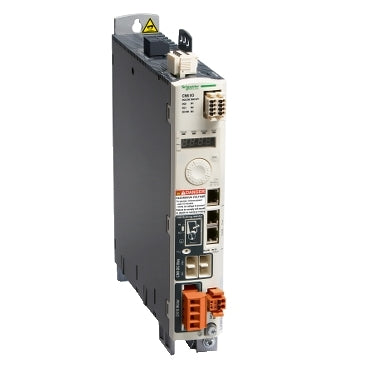
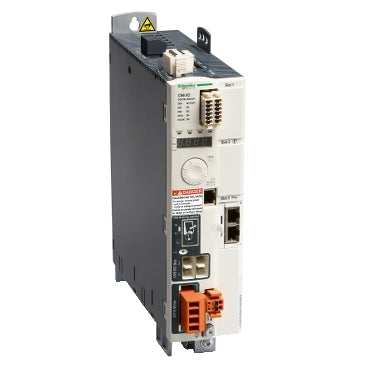
This product is part of the Lexium 32 range, an offer of motion servo drives for machines from 0.15kW to 7kW. The AC motion servo drive for one axis, features with an integrated EMC filter, compact drive with analogue inputs and pulse train. It provides 1 capture, 2 safety, 4 logic discrete inputs and 2 discrete outputs. Thanks to its compact design this servo drive enables to save on cabinet space and size, reduces the machine footprint and decreases costs. It is a motion servo drive with a rated supply voltage of 200V to 240V, 380V to 480V (three phase), a continuous output current of 24A at 8kHz and a continuous power of 13000W at 400V. It is furnished with terminal for electrical connection and three RJ45 connectors for CANmotion, CANopen, and Modbus, integrated communication interfaces. It is an IP20 rated product. Its dimensions are 108mm (Width) x 237mm (Depth) x 270mm (Height). It weighs 4.8kg. This product is certified by CE, CSA, RoHS, TUV and UL. It meets EN/IEC 61800-3 and EN/IEC 61800-5-1 standards. This product is compatible with servo motors BMH and BSH. Servo drive range with four servo drive models and two servo motor families plus an intelligent selection of options. It provides you with the drive and motor combination that has exactly the right power, performance and functionality.
Main
| Characteristic | Value(s) |
|---|---|
| Range of Product | Lexium 32 |
| Device short name | LXM32A |
| Product or Component Type | Motion servo drive |
| Format of the drive | Book |
| Phase | Three phase |
| [Us] rated supply voltage | 200...240 V - 15...10 % 380...480 V - 15...10 % |
| Supply voltage limits | 170â¦264 V 323â¦528 V |
| Supply frequency | 50/60 Hz - 5...5 % |
| Network Frequency | 47.5...63 Hz |
| EMC filter | Integrated |
| Continuous output current | 24 A 8 kHz |
| Output current 3s peak | 72 A 208 V 5 s 72 A 480 V 5 s |
| Continuous power | 6500 W 208 V 13000 W 400 V 13000 W 480 V |
| Nominal power | 5 kW 208 V 8 kHz 7 kW 400 V 8 kHz 7 kW 480 V 8 kHz |
| Line current | 21.1 A 34 % 208 V, with external line choke 1 mH 22.5 A 45 % 400 V, with external line choke 1 mH 19.5 A 55 % 480 V, with external line choke 1 mH 21.9 A 106 % 208 V, without line choke 17.3 A 126 % 400 V, without line choke 14.6 A 129 % 480 V, without line choke |
Complementary
| Characteristic | Value(s) |
|---|---|
| Switching frequency | 8 kHz |
| Overvoltage category | III |
| Maximum leakage current | 30 mA |
| Output voltage | <= power supply voltage |
| Electrical isolation | Between power and control |
| Type of cable | Single-strand IEC cable 122 °F (50 °C)) copper 90 °C XLPE/EPR |
| Electrical connection | Terminal 3 mm², AWG 12 CN8) Terminal 5 mm², AWG 10 CN1) Terminal 5 mm², AWG 10 CN10) |
| Tightening torque | CN8 4.4 lbf.in (0.5 N.m) CN1 6.2 lbf.in (0.7 N.m) CN10 6.2 lbf.in (0.7 N.m) |
| Discrete input number | 1 capture 2 safety 4 logic |
| Discrete input type | Capture CAP Logic DI Safety compliment of STO_A, compliment of STO_B |
| Sampling duration | DI 0.25 ms discrete |
| Discrete input voltage | 24 V DC capture 24 V DC logic 24 V DC safety |
| Discrete input logic | Positive compliment of STO_A, compliment of STO_B)< 5 V > 15 V EN/IEC 61131-2 type 1 Positive DI)> 19 V < 9 V EN/IEC 61131-2 type 1 Positive or negative DI)< 5 V > 15 V EN/IEC 61131-2 type 1 |
| Response time | <= 5 ms compliment of STO_A, compliment of STO_B |
| Discrete output number | 2 |
| Discrete output type | Logic DO)24 V DC |
| Discrete output voltage | <= 30 V DC |
| Discrete output logic | Positive or negative DO)EN/IEC 61131-2 |
| Contact bounce time | <= 1 ms compliment of STO_A, compliment of STO_B 2 µs CAP 0.25 µs...1.5 ms DI |
| Braking current | 50 mA |
| Response time on output | 250 µs DO)discrete |
| Control signal type | Servo motor encoder feedback |
| Protection type | Against reverse polarity inputs signal Against short-circuits outputs signal |
| Safety function | STO (safe torque off), Integrated |
| Safety level | SIL 3 EN/IEC 61508 PL = e ISO 13849-1 |
| Communication interface | CANmotion, Integrated CANopen, Integrated |
| Connector type | RJ45 (labelled CN4 or CN5) CANmotion RJ45 (labelled CN4 or CN5) CANopen |
| Method of access | Slave |
| Transmission rate | 1 Mbps 13.1 ft (4 m) CANopen, CANmotion 125 kbps 1640.4 ft (500 m) CANopen, CANmotion 250 kbps 820.2 ft (250 m) CANopen, CANmotion 50 kbps 3280.8 ft (1000 m) CANopen, CANmotion 500 kbps 328.08 ft (100 m) CANopen, CANmotion |
| Number of addresses | 1â¦127 CANopen, CANmotion |
| Communication service | 1 receive SDO CANmotion 1 transmit SDO CANmotion 2 PDOs conforming to DSP 402 CANmotion 2 SDOs receive CANopen 2 SDOs send CANopen 4 configurable mapping PDOs CANopen CANopen device profile drives and motion control CANopen, CANmotion Emergency CANopen, CANmotion Event-triggered, time-triggered, remotely requested,sync (cyclic), sync(acyclic) CANopen Node guarding, heartbeat CANopen Position control mode CANmotion Position control, speed profile, torque profile and homing mode CANopen Sync CANmotion |
| Status LED | 1 LED (Red) servo drive voltage 1 LED error 1 LED RUN |
| Signalling function | Display of faults 7 segments |
| Marking | CE |
| Operating position | Vertical +/- 10 degree |
| Product compatibility | Servo motor BMH 5.5 in (140 mm), 2 Servo motor BMH 5.5 in (140 mm), 3 Servo motor BMH 7.5 in (190 mm), 1 Servo motor BMH 7.5 in (190 mm), 2 Servo motor BMH 7.5 in (190 mm), 3 Servo motor BMH 8.07 in (205 mm), 3 Servo motor BSH 5.5 in (140 mm), 2 Servo motor BSH 5.5 in (140 mm), 3 Servo motor BSH 5.5 in (140 mm), 4 |
| Width | 4.3 in (108 mm) |
| Height | 10.6 in (270 mm) |
| Depth | 9.3 in (237 mm) |
| Product Weight | 10.6 lb(US) (4.8 kg) |
Variable Speed Drive Altivar ATV312 - 15kW - 32kVA - 492 W - 380..500 V - 3-Phase Supply
Variable Speed Drive Altivar ATV312 - 7.5kW - 18kVA - 269W - 380..500 V - 3-Phase Supply
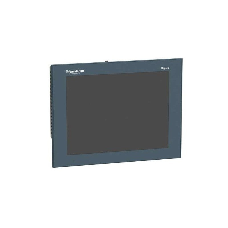
Advanced touchscreen panel 800 x 600 pixels SVGA- 12.1" TFT - 96 MB
Variable Speed Drive Altivar 71 - 5.5kW-7.5hp - 480V -EMC filter-whitout Graphic Terminal
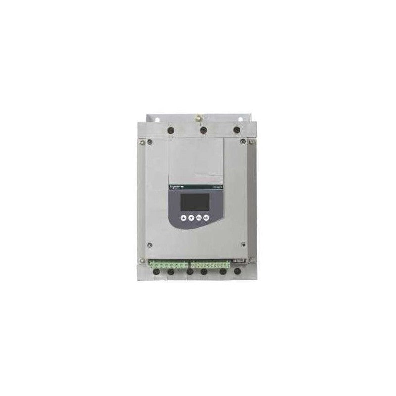
This Altistart 48 soft start/soft stop unit is a controller with 6 thyristors used for torque-controlled soft starting and stopping of three-phase asynchronous motors. It offers soft starting and deceleration functions along with machine and motor protection functions, as well as functions for communicating with control systems. It works at a rated supply voltage from 230V to 415V AC and up to 110A rating. Altistart 48 torque control enables starting without mechanical stress and smooth control of hydraulic transitions, with a single acceleration ramp making adjustments is quick and easy, whatever the load. If connected in the motor supply line it is suitable for motors with power rating up to 55kW (at 400V) for standards applications and 45kW (at 400V) for severe applications. If connected to the motor delta terminals it is suitable for motors with power rating up to 90kW (at 400V) for standards applications and 75kW (at 400V) for severe applications. It weighs 8.3kg and its dimensions are, 190mm wide, 290mm high, 235mm deep. It is designed for use in the most common applications for centrifugal machines, pumps, fans, compressors and conveyors, which are primarily to be found in the construction, food and beverage and chemical industries. It complies with IEC/EN 60947-4-2 standard and is certified CE, UL, CSA, DNV, C-Tick, GOST, CCC, NOM, SEPRO, and TCF. The Altistart 48 is connected directly to the Modbus bus via its RJ45 connector port, It can also be connected to Ethernet, Fipio, Profibus DP and DeviceNet networks via a module (bridge or gateway) to order separately. It is designed to be mounted in vertical position (+/- 10 °) on a panel, thanks to 4 fixing holes. Altistart 48 delivers high performance with its Torque Control System (TCS) for controlled starting and deceleration, an easy integration in enclosures and control systems. This range provides also continual improvement of your machine operation by reducing mechanical or hydraulic stress and limiting energy loss and temperature rise, plus more.
Main
| Characteristic | Value(s) |
|---|---|
| Range of product | Altistart 48 |
| Product or component type | Soft starter |
| Product destination | Asynchronous motors |
| Product specific application | Heavy duty industry and pumps |
| Device short name | ATS48 |
| Utilisation category | AC-53A |
| Ue power supply voltage | 230...415 V - 15...10 % |
| power supply frequency | 50...60 Hz - 5...5 % |
| Motor power kW | 55 kW at 230 V connection to the motor delta terminals for standard applications 55 kW at 400 V connection in the motor supply line for standard applications 75 kW at 400 V connection to the motor delta terminals for severe applications 90 kW at 400 V connection to the motor delta terminals for standard applications 22 kW at 230 V connection in the motor supply line for severe applications 30 kW at 230 V connection in the motor supply line for standard applications 45 kW at 230 V connection to the motor delta terminals for severe applications 45 kW at 400 V connection in the motor supply line for severe applications |
Complementary
| Characteristic | Value(s) |
|---|---|
| Device connection | To the motor delta terminals In the motor supply line |
| Protection type | Phase failure: line Thermal protection: motor Thermal protection: starter |
| Standards | IEC 60947-4-2 |
| Product certifications | C-Tick GOST SEPRO NOM 117 CSA TCF DNV CCC UL |
| Marking | CE |
| Discrete input number | 5 |
| Discrete input type | PTC, 750 Ohm at 25 °C (Stop, Run, LI3, LI4) logic, <= 8 mA 4300 Ohm |
| Discrete input logic | Positive logic Stop, Run, LI3, LI4 at State 0: < 5 V and <= 2 mA at State 1: > 11 V, >= 5 mA |
| Minimum switching current | 10 mA at 6 V DC for relay outputs |
| Discrete output number | 2 |
| Discrete output type | (LO1) logic output 0 V common configurable (LO2) logic output 0 V common configurable (R1) relay outputs fault relay NO (R2) relay outputs end of starting relay NO (R3) relay outputs motor powered NO |
| Analogue output type | Current output AO: 0-20 mA or 4-20 mA, impedance <500 Ohm |
| Communication port protocol | Modbus |
| Connector type | 1 RJ45 |
| Communication data link | Serial |
| Physical interface | RS485 multidrop |
| Transmission rate | 4800, 9600 or 19200 bps |
| Function available | External bypass (optional) |
| Operating position | Vertical +/- 10 degree |
| Height | 290 mm |
| Width | 190 mm |
| Depth | 235 mm |
| Product weight | 8.3 kg |
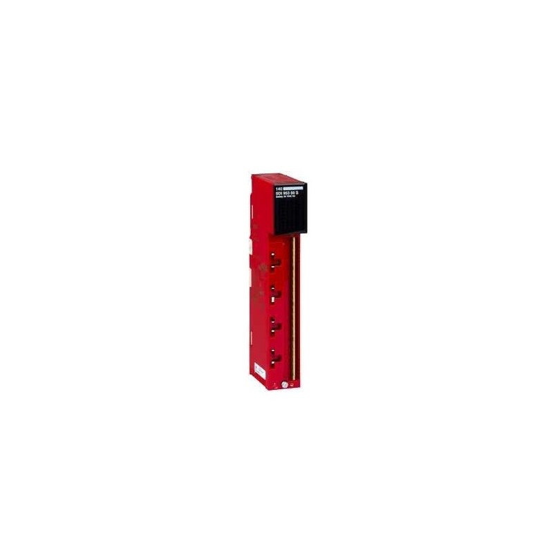
Main
| Characteristic | Value(s) |
|---|---|
| Range of Product | Modicon Quantum automation platform |
| Product or Component Type | Safety dc discrete input module |
Complementary
| Characteristic | Value(s) |
|---|---|
| Discrete input number | 16 |
| Group of channels | 1 |
| Logic input | Positive (sink) |
| Discrete input voltage | 24 V DC |
| Voltage state 1 guaranteed | 11...30 V DC |
| Voltage state 0 guaranteed | -3...5 V DC |
| Current state 1 guaranteed | >= 3 mA |
| Current state 0 guaranteed | <= 1.5 mA |
| Sensor power supply | 19.2â¦30 V |
| Addressing requirement | 7 input words |
| Input impedance | 3675 Ohm |
| Absolute maximum input | 30 V |
| Response Time | <= 25 ms from state 0 to state 1 <= 25 ms from state 1 to state 0 |
| Protection Type | By internal rectifier |
| Associated fuse rating | 1 A, fast blow |
| Power dissipation | 2.75 W + (0.25 x number of points on) |
| Isolation between group and bus | 1500 Vrms for 1 minute |
| Checks | Diagnostic of internal channel fault System failure Broken wire detection |
| Local signalling | 1 LED (green) for bus communication is present (Active) 1 LED (red) for external fault detected (F) for input status 16 LEDs (green) for system failure, diagnostic of internal channel fault 16 LEDs (red) |
| Marking | CE |
| Bus current requirement | 550 mA |
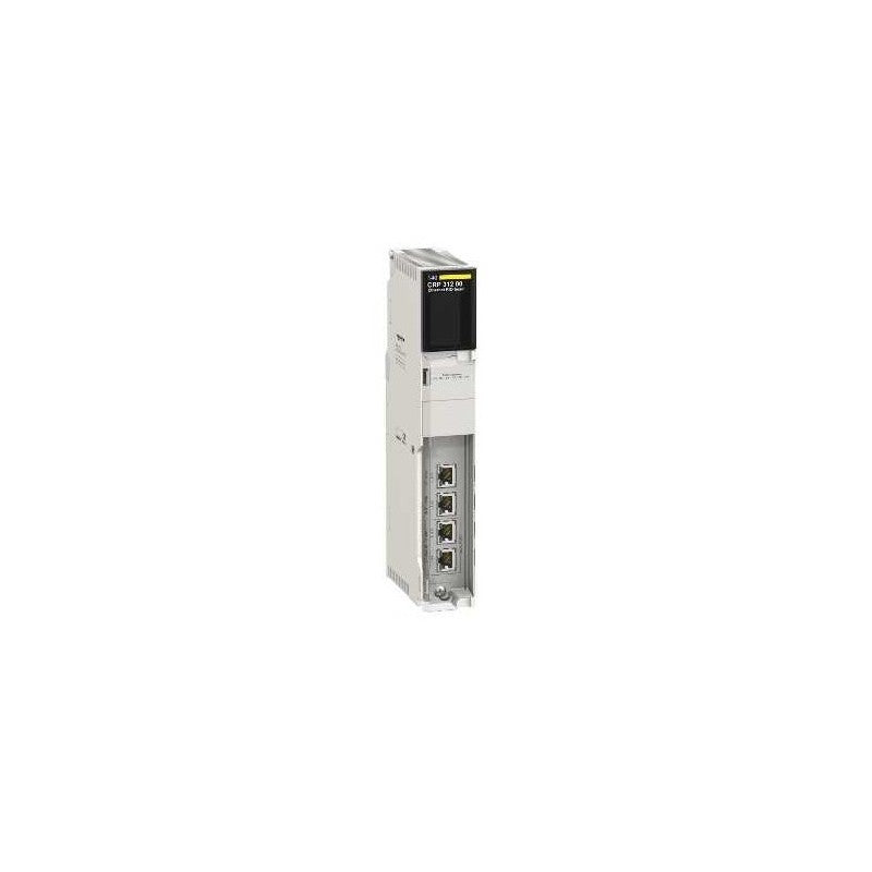
Main
| Characteristic | Value(s) |
|---|---|
| Range of Product | Modicon Quantum |
| Product or Component Type | Ethernet RIO head for Quantum |
| Number of port | 4 |
| Integrated connection type | Ethernet IP/Modbus TCP service port Ethernet IP/Modbus TCP interlink port Ethernet IP/Modbus TCP device network |
| Communication Port Protocol | Ethernet IP/Modbus TCP |
| Communication Service | Diagnostics for remote I/O devices Configure IP parameters RSTP support Configuration for remote I/O devices Allows PLC to connect to an Ethernet network |
Complementary
| Characteristic | Value(s) |
|---|---|
| Topology | Daisy chain loop |
| Local signalling | 1 LED (green) for activity 1 LED (green) for ready 1 LED (green/red) for module status (Mod Status) 1 LED (green/red) for network communication status (Net Status) |
| Product Compatibility | 140CPU65150 140CPU65260 140CPU65160 140CPU67261 140CPU67160 |
| Environmental characteristic | Standard environment Hazardous location class I division 2 EN/IEC 61131-1 |
| Width | 6.6 in (167 mm) |
| Height | 2.0 in (50 mm) |
| Product Weight | 1.221 lb(US) (0.554 kg) |
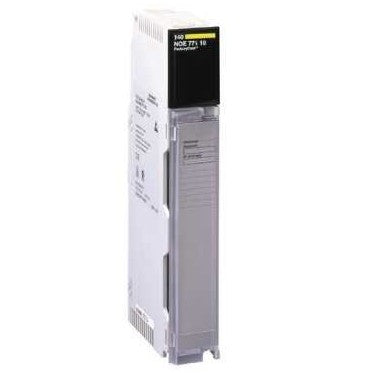
Main
| Characteristic | Value(s) |
|---|---|
| Range of Product | Modicon Quantum automation platform |
| Product or Component Type | Ethernet network TCP/IP module |
| Concept | Transparent Ready |
| Web server | Class C30 |
| Web services | Rack viewer FactoryCast configurable Data editor |
| Communication Service | Bandwidth management NTP time synchronization SNMP network management I/O scanning Modbus TCP messaging SMTP e-mail notification FDR server Global Data |
| Communication Port Protocol | Ethernet Modbus TCP/IP |
| Physical interface | MT/RJ - 100BASE-FX fiber optic RJ45 - 10BASE-T/100BASE-TX twisted pair |
| Transmission Rate | 10/100 Mbit/s |
Complementary
| Characteristic | Value(s) |
|---|---|
| Redundancy | Yes hot standby redundant architecture |
| Supply | Via the power supply of the rack |
| Marking | CE |
| Local signalling | 1 LED for 10 Mbps or 100 Mbps data rate (10 MB/100 MB) 1 LED for collision detection (Coll) 1 LED for download mode (Kernel) 1 LED for Ethernet module fault (Fault) 1 LED for Ethernet network status (RUN) 1 LED for full-duplex mode (Fduplex) 1 LED for module ready (Ready) 1 LED for network active (Link) 1 LED for rack operational (Active) 1 LED for transmission/reception activity (TxAct/RxAct) |
| Current consumption | 750 mA 5 V DC |
| Module format | Standard |
| Product Weight | 0.761 lb(US) (0.345 kg) |
We at PLC Direct offer a series of these Schneider Electric PLCs, including outdated models, to ensure that you have access to the exact products you need. So whether you’re running a newer or an older model, you can rest assured that we have something that’ll help you replace or repair your existing system. This way, you won’t need to perform a full overhaul of your automation devices before you’re good and ready to. Additionally, we make it a point to be transparent about Schneider spare part availability so that you always know the potential lead times. Shop below to learn more about this as well as our other industrial automation products for sale. We’ll be your number one resource for all your PLC needs.